1. Graphical Editor
The program is equipped with a universal graphics editor, reminiscent in its interface, Autocad or Solidworks. The sequence of formation of an analytical model design can be divided into four stages. Initially, the skeletal scheme of the structure should be represented. The skeleton scheme consists of nodes and lines connecting them, and looks very similar to the analytical model. But in contrast to the analytical model, its lines is really just a lines, rather than beams, plates and so on. This is really a skeleton structure, on which subsequently will be threaded different finite elements. "Structure dressing - the second stage of the formation of a analytical model. Once the scheme gets the flesh, it is possible to apply external links and loads. The division into stages purely conventional - modes of the editor is available for use in any sequence.
The program reads a DXF-files, and allows you to import volumetric tetrahedral mesh from COSMOS
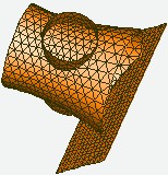
1.2. Shells generation
The program allows you to create different kinds of shells, covering them with high-quality triangular meshes. 8 different types of generation facilities:
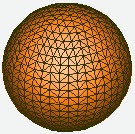
Generation of spheres
Sphere is generated by layers which are parallel to the main coordinate plane XOY, and has two poles, which lie on a line parallel to the axis Z.
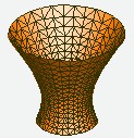
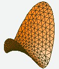
Generation of surfaces of revolution
The equation of the shell is defined as the dependence of the shell radius from the linear coordinate along the shell axis, measured from the beginning. The shell generated by the layers which are orthogonal to the shell axis. All layers have the same number of divisions along the circle. The shell is generated in such a way that the size of grid cells in the meridional direction and the cyclic coordinates in any point of the shell are the same.
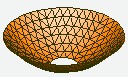
Generation of shallow shells of revolution
The equation of the shell is defined as the dependence of the height of the shell point above the plane orthogonal to the shell axis and passing through the shell origin, from the point radius. The shell layers are generated orthogonal to the shell axis. Each layer has on 6-cell more than the preceding one. The shell is generated in such a way that the sizes of grid cells in the meridional direction and along cyclic coordinates of any point of the shell are the same.
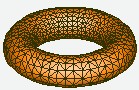
Генерация трансляцией
The surface of such a shell is formed by translation along a curve forming guide. A typical example of such a surface - a torus.
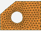
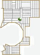
The generation of planes
Before you start generating a plane contour must be formed with a detailed sectionalization. The contour generated of the area can be multiply connected. You can enter the concentrators and fixed nodes (i.e. nodes with fixed coordinates) to regulate condensations or rarefactions of generated mesh.
Generation of quadric surfaces
If the surface is described by quadratic equation (ellipsoid, parabolic, hyperboloid), it suffices to define a contour of the generated surface. The program itself will determine the equation of the surface and pulls at her triangular mesh well. The contour generated surface can be multiply. You can enter the concentrators and fixed nodes (i.e. nodes with fixed coordinates) to regulate condensations or rarefactions of generated mesh.
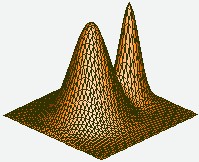
Generation of surfaces given by algebraic expression
Before you start generating a plane contour must be formed. The equation of the surface is defined as a function of z = z (x, y) in a local basis. The contour generated surface can be multiply. You can enter the concentrators and fixed nodes (i.e. nodes with fixed coordinates) to regulate condensations or rarefactions of generated mesh.
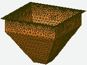
The generation of surfaces in the assembly
Allows you to generate an assembly of shell structures composed of planes. Generated of assembly does not require a preliminary contours division. The program itself provides a conjugation of planes having a common border. The contour generated surface can be multiply. You can enter the concentrators and fixed nodes (i.e. nodes with fixed coordinates) to regulate condensations or rarefactions of generated mesh.
Construction of the intersection
The program allows you to build the shells intersection, intersections with the lines and cut them with other objects.
1.3. Loading surfaces
Loading surfaces are not elements of analytical scheme. This is only an auxiliary means which facilitate the procedure of transferring of various distributed loads to the structure. The program looks for all the planes, which may be imposed on a pre-marked lines of skeleton and builds on them envelopes circuits connected regions. Subsequently, the thus formed surface may be accompanied by a variety of distributed loads. Distributed load transmitted to the construction through a loading surface is converted to a system of forces, determined as response on movement of the loading surface as a rigid body, or loading surface is replaced by a flexible membrane.
Loading surfaces allows you to automate assignment of distributed wind loads on the structural stand, etc.
1.5. Loads
Static, dynamic, parametric, and moving static loads are used to rolling-on the lanes and moving dynamic loads can be applied to structure. By the method of application of the load can be divided into 4 groups:
Nodal loads. It is local forces, lical moments and displacements of supports.
Local loads. - loads applied directly to the finite elements. It may also be local forces and moments, distributed loads, fixed, variable, changing by the known law, given on whole finite element or partly thereof, dead weight, temperature loads (including temperature difference), wind load.
the load applied to the triangular element of the two parametric elastic foundation:


the load applied to the rectangular element of the two parametric elastic foundation:


the load applied to the mass element:


Load applied to the load surfaces. It can be distributed load varying by the given law, wind loads, the resulting forces and moments. The program operates with two types of loading surfaces: a surface (planes) generated by the user explicitly and shells surfaces. First used as an aid to transfer loads to the nodes of structure. The second allow you to work with the shell surface as a single object.
The structural loads. This is a load applied to the whole construction, such as acceleration, wind and seismic effects. The peculiarity of the structural loads is that - for their assignments it is not necessary to allocate the individual elements (nodes, finite elements, the surface loading) - load is given once on the entire structure.
The mobile load. The mobile load is correspond a series of forces, linked to a certain route by which this load can be moved. It can be formed a several routes of the load at the same time. If necessary, you can synchronize the entry of the loads on the various routes by specifying a relative time delay of entry load on the route.
2. Editor of beam sections
The program has a very simple and easy editor of the sections. It supports the formation of two types of sections:
Arbitrary cross-section. The contour of arbitrary cross-section is formed form the closed polygons and circles. The rounding can be inscribed at the vertices of the polygons. The program supports the processing of multiply connected (with hole) sections. The longitudinal reinforcement can be defined in the beam section.
The peculiarity of the arbitrary cross-sections regime is that the moment of inertia of free torsion is calculated by directly solving the Poisson problem for a given contour. The program automatically generates a triangulation of cross section and solves the problem of the theory of bars torsion using finite element method.
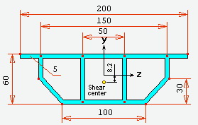
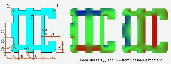
Thin-walled cross-sections. Thin-walled section is formed as a series of interconnected straight lines. The cross section can be multiply connected (composed of several closed loops) and has a branches. It can be included rounding in the corners of the pairs segments conjugation.
All the characteristics of the cross section are calculated on the assumption that the thickness of the walls of the cross section significantly smaller than its dimensions. The program calculates all the characteristics of cross sections, the shear center, build diagrams of sartorial areas.
The program supports the formation of assortments and maintain a database of bar sections.
3. Combinations of loads
Combinations - finding the most unfavorable combination of loads in concordance with various calculation factors. The calculated combination may include simultaneously static, harmonic, pulsation wind, seismic loading, a stationary random process, the dynamic random effects, lanes rolling.
Calculation of the unfavorable combination of loads is performed based on the combination of graphs. The graph is represented by combinations of a set of points that are pairwise connected by segments of curves (arcs). Each arc of the combination graph means a loading, on the action of which had been calculated. The combination of loads is depicted in the graph as a continuous sequence of arcs forming a path from the initial vertex to the destination. The result of calculation for each item are the maximum (minimum) value for each selected calculation factors (force, stress), the corresponding forces and stress and loadings combinations, which ensured the extreme value of the estimated factors.