Selena is a universal software for design and analysis of buildings and industrial structures. It allows to construct analytical models of any degree of complexity, perform strength and buckling analysis and optimize parameters of dynamic systems.

The program provides strength analysis module, buckling of beams and shells and a wide spectrum of dynamic calculations (see Capabilities). Some of the important advantages of the software include straightforward and easy-to-use options for shell creation, as well as a huge set of tools for high-quality mesh generation. Local forces and moments, displacements (including dynamic), various distributed loadings, thermal loadings, transient loadings, wind and seismic influences can be applied to the structure in a very convenient way. The software then automatically converts the specified loadings to nodal equivalents.


Static analysis

Determination of the deflected mode of structures as affected static effects. As the load for static analysis can be given concentrated forces, concentrated moments, displacements of supports, the load distributed over a given law, volumetric loading, distributed moments, thermal expansion, temperature difference, wind load, the load transmitted through the loading surface.

Static analysis can be performed once for a series of independent loadings. The result of static analysis are nodes displacements, forces in the beam elements, stresses in the beam, plates, shells and three-dimensional elements, the diagrams nodes equilibrium, supporting reaction of the construction. The results of static analysis can be displayed either on the individual loadings, or by combinations of loadings.

( ReadReduce )


Longitudinal bending

Longitudinal bending - the geometrically nonlinear analysis, which allows to take into account longitudinal bending of a beam as well as shell systems.

The calculation is performed in several iterations. In the first step, the static calculation for a given combination of loads (a request for the desired combination of loads shall be issued before the beginning of the analysis). Forces in structural elements, identified in this iteration, served as a parameter load for the next iteration, etc. The calculation can be extended to as long as the difference between the parametric load between successive iterations is more than a given error, or do not exceed the specified number of iterations.

The result of analysis (taking into account the longitudinal bending) are nodal displacements, forces in the beam elements, stresses in the breams, plates, shells and three-dimensional elements, nodes equilibrium diagrams, supporting reaction of the construction.

( ReadReduce )


Buckling

Buckling analysis of the construction can be carried out in three modes: linear analysis, nonlinear analysis and buckling verification of the beam structures taking into account initial curvature of the beam elements.

The linear buckling analysis permits to determine the buckling critical parameters of the global instability of the structure. The calculation is performed by iteration - all loads are multiplied by the same factor up to pass by the structure state of instability. The result of linear buckling analysis are the critical buckling parameter (the safety factor for stability), as well as buckling lengths and flexibilities of the beam elements.

Nonlinear analysis per stability it is advisable applied to structures with initial imperfections. The peculiarity of analysis of such structures is that the ratio between the longitudinal forces (stresses) in the loading process in the individual elements can vary considerably (the shells include to this category primarily). That is, in contrast to the linear analysis, forces (stresses) in the structure elements at the moment of loss of stability cannot be obtained by multiplying the forces (stresses), calculated at some initial state, on the same factor. Nonlinear buckling analysis specifies the stresses state of structure by recalculation it taking into accounts a longitudinal bending of elements at each stage of loading.

The peculiarity of beam structures is that its elements are almost always lose stability earlier than predicted by the linear analysis. The reason of this is the presence of small initial random distortions and attachment eccentricities of beams. Therefore, even if beam is central compressed, the bending moments appears, and if fiber stresses at some point exceed the yield strength of the material, the loss stability process begins to develop with catastrophic speed. The program offers a special mode analysis with a slightly curved beams. Depth of irregularities can be calculated either in accordance with Eurocode 3, or SNiP II-23-81, or CP 16.13330.2011. The result of analysis are the maximum fiber stress in the rods. Thus, to assess the stability of the beam element it is sufficient to compare obtained fiber stress with yield stress of the material from which beam element is made.

( ReadReduce )


Determination of the buckling length of the rod elements

Verification of the local stability of rod elements is one of the most important checks needed to ensure reliable work of building structures. Virtually no calculation can do without this check. At the same time, every calculator knows how much uncertainty this test carries. The problem is related to the fact that for its execution for each bar the checker must be set by the so-called "buckling length". As a rule, software systems are able to issue this parameter (buckling length is a byproduct of testing on overall structural buckling). But very often, the calculated values are outside of reasonable. In particular, for lightly loaded rods, the program can produce huge quantities that do not fit into any natural understanding of the nature of this test. A similar situation occurs if a weak rod, which loses stability much earlier than the whole structure (degenerative form of buckling). In this case, the program calculates the buckling parameters of all other rods, focusing on this underestimated critical value found, producing a complete absurdity.

Practice shows that the virtually calculated by the program values of the buckling lengths can be used for no more than 5-10% of the rod elements included in the structure. For the remaining elements, the calculator must refer to various reference books and standards, which do not always cover all possible cases. Unfortunately, only a very experienced designer can know in this situation, understand when you can use the data provided by the analysis, or refer to reference books. Therefore, checking the local buckling of the rod elements often resembles fortune-telling on the coffee grounds.

Physically, the buckling length of the rod is the distance between a pair of neighboring nulls in the bending moment diagram of rod subjected to buckling. This, it is considered, an arbitrary rod is brought to the pinned ends rods. To calculate the buckling length of an individual rod, it suffices to solve for it the problem of buckling about eigenvalues under known boundary conditions of the rod. The last condition is the main problem of finding the buckling lengths - for the simplest types of rod fastening (hinged, cantilevered, etc.) these conditions are well known, while for an arbitrary rod, which is an element of a large structure, this is not an easy task. In general, in order to establish the effect of the rest of the structure on the rod, a procedure is required that is equivalent in cost to one static analysis. It is clear that if the structure is large enough, the task becomes almost unaffordable. Therefore, in order to somehow get closer to the solution of this task, they go to a trick - they make a calculation of the overall stability of the structure, proportionally changing the forces in all its elements. As a result of one such calculation, a critical force is obtained for each component of the structure, turning a blind eye to the fact that the boundary conditions at the ends of a concrete rod are provided by the reaction of a weakened structure - if the greater the forces in the elements of the structure, then weaker it resists to shifts and turns. As a consequence, the calculated lengths are always overstated.

Within the framework of this project, a unique algorithm has been developed, which makes it possible to very quickly find the buckling lengths of all rod elements of the structure corresponding to the real stress state. That is, for each rod, the real resistance of the remaining part of the structure at the actual stress state is taken into account. Thanks to this approach, the problem of "huge buckling lengths" disappears. The buckling lengths can be calculated independently of each other for both main section axes. The concept of "buckling length" can be quite naturally extended to unloaded and even stretchable elements. The calculated buckling lengths can be automatically transferred to the stage of checking and selecting of sections, which allows you almost completely automate this procedure.

( ЧитатьСвернуть )


Interaction accounting of the construction with the base

The program provides several possibilities accounting for elastic properties of the subgrade. The simplest version of Winckler base can be implemented using finite element of linear elastic single-point restriction. The main imperfection of the Winckler base model is that it ignores the distribution properties of the soil. An alternative to the using Winckler base model is elastic half-space model or a model of the elastic layer. In this case, the base volume modeled by a set of finite elements, the properties of which depend on the depth of the overlying layer.

The obvious disadvantage of this model is a significant increase in the size of the model (the number of variables going on the base description may significantly exceed the number of variables of the main structure). At present there are several mechanical models of the base allowing on the one hand take into account the distribution properties of the soil, and on the other - do not require large computational cost. One such model is the base model with two coefficients of soil reaction (two-parameter model). The elastic half- space model by the system of planar finite elements, whose properties depend on the underlying soil layers.

( ReadReduce )


Free vibrations

Determination of eigenfrequencies and mode shapes of construction. Calculation on free oscillations can be executed in two modes - the calculation of systems with concentrated masses and masses of distributed systems.

The eigenfrequencies and mode shapes can be determined in light of the longitudinal stress on the given combination of static loadings. If the calculation is performed in the regime of concentrated masses, the program will automatically reduce the masses of structural elements to the specified nodes. If necessary, the mass of structural elements can be added to these nodes.

The fundamental difference between systems with distributed masses from the systems with concentrated masses is that the spectrum of systems with distributed masses is unlimited. Therefore, to perform the calculation on the free vibration in distributed masses mode, you must first specify a frequencies range, in which will the eigenvalues will be searched. For calculation in distributed masses mode the program uses the qualitative method for determining the eigenvalues of the system.

( ReadReduce )


Mass determination

Local mass determination by the known eigenfrequencies of the structure (fitting the mass of the system).

Calculation mode allows you to "adjust" concentrated masses of the system, to previously assigned frequency spectrum. One of the possible applications of this mode - specify the masses of the system by the measured frequencies. But a more likely application is to fit frequencies of the system with lumped masses to the frequencies of the system with distributed masses.

A number of dynamic calculations may be executed only in the concentrated mass. On the other hand the distributed mass analysis makes it possible to determine the natural frequencies with any degree of accuracy. Thus, the definition of mass analysis (mass fitting) provides a convenient opportunity to move properly from systems with the distributed masses to the systems with concentrated masses.

( ReadReduce )


Amplitude-frequency response

This version of analysis allows us to construct the amplitude-frequency response in certain points of the system due to the given harmonic effects.

As the effects may be a harmonic oscillation, inertial effects (the amplitude of the impact proportional to the square of the frequency), the impact of wind pulsation (as the amplitude of the dynamic effects selected wind pulsation component) and wind response (as the amplitude of the dynamic effects selected resonant load acting across the wind flow and resulting by the disruption of alternating vortices over the construction mast or tower type).

The calculation is performed by expanding by the forms of vibration. The individual coefficient of energy absorption may be done for each vibration mode.

( ReadReduce )


Dynamic absorber of vibration

This version of analysis makes it possible interactively configure the dynamic dampers of vibration. For this purpose, an option to calculate the dynamical systems with attached masses is implement.

The calculation of dynamic absorbers of vibration based on the assumption that the added mass interacts with each harmonic of vibrations separately. In this case the problem reduces to n independent tasks (n - number of dynamic degrees of freedom of the basic structure), each of which represents a system of two masses - the reduced mass of the main system to the point of damper suspension by the i-th form of natural oscillations and the mass of absorber. Since in practical problems damper is set to one of the frequencies of the main system, the influence of this particular mode will be dominant, and then the error of the absorber interaction with other modes at a given frequency can be neglected.

This mode of calculation is exploratory. It allows you to estimate the parameters of the dynamic absorbers before they are introduced into the construction. To check the absorber setting by precise methods you should use the option "Forced harmonic vibrations”."

( ReadReduce )


Dynamic time-dependent effects

Calculations on arbitrary (time-varying) dynamical effects.

This version allows you to perform dynamic analysis of structures on a range of effects, given its law changes over time. As effects can be selected as follows:

  • ree oscillations with given initial static and dynamic conditions
  • impulse
  • impulse of finite duration
  • triangular impulse
  • suddenly applied load
  • load, increasing linearly with time up to a certain point and then remains constant
  • sinusoidal effect of finite duration
  • sinusoidal effects of finite duration + suddenly applied force
  • series of repetitive rectangular impulses
  • sawtooth load
  • harmonic excitation with amplitude increasing linearly with time up to a certain point and then remains constant
  • harmonic excitation with frequency increasing proportional to the time and amplitude increasing with the square of time up to a certain point, after which the remaining constant (simulation of the pickup of the engine)
  • load, defined by a polynomial in powers of time
  • package of sinusoidal waves
  • stationary random process, the spectral function is given by a polynomial in powers of frequency
  • stationary random process, the spectral function is determined by the Davenport spectrum
  • stationary random process, the spectral function is determined by the Panofsky spectrum
  • seismic effect

Dynamic disturbance can be set either by amplitude values of concentrated forces applied to the nodes (the amplitude values of the forces are multiplied by a function of time, given by type of impact), or by the dynamic displacements of supports (a function of acceleration of the base is given in this case).

For stationary random processes (wind pulsations, seismic, etc.) the program itself implement a random process on the basis of its spectral density.

( ReadReduce )


Dynamic processes with changing end conditions

Often the calculation of dynamical systems in the Random dynamic effect arises necessity to change the loading conditions or structure end conditions directly in the deformation process. The program provides an opportunity to create a new task or a new loading with initial conditions for which are the values of structure nodes displacements and velocities, taken at some point in time.

Thus, it is possible to build an arbitrarily long chain of solutions, each of which sequentially transfers its final state, as the initial conditions for a subsequent process.

( ReadReduce )


Harmonic oscillations

Determination of the deformation mode from the harmonic effects. The load may act as concentrated forces, concentrated moments and displacements of supports.

It can be carried out calculations on a series of independent harmonic disturbances with different frequencies of exposure at the same time. Forced harmonic analysis allows taking into account the frequency-independent internal friction in the structure elements. It can be set individually the absorption of energy for each structural element. The dynamic vibration absorbers can be connected to the system in dynamic harmonic analysis.

( ReadReduce )


Monitoring of cable systems

The task of monitoring is to give an opinion on the functionality of the structure. For large structures containing cable-stayed elements, this problem is complicated by the fact that rope tension measurements have to be made over a considerable period of time. Therefore, as a rule, it is impossible to provide the reading of measuring devices at the same temperature. As a result, take the readings of sensors cannot be brought to a "common denominator".

This mode of analysis allows you to reduce the results of such measurements to some single given temperature. The next step may be issuing recommendations for bringing the structure into proper condition. This task is successfully solved by calculating the Rope tension adjustment mode, which allows you to build a rope adjustment program that provides reduce the system to a design state in a countable number of steps.

( ЧитатьСвернуть )


Stationary random effects

Determination of the deformation mode of the structures under the influence of a stationary random effects with known spectral density.

The calculation is made by direct integration of the output variances of the calculated quantities (displacements, forces, stresses, support reactions) by a given energy spectrum of the input. Frequency range is divided into a number of intervals within which its own spectral function can be given, and set the required accuracy of integration.

Программа обрабатывает 4 разновидности энергетических спектров:

  • Davenport spectrum
  • Panovsky spectrum, for vertical component of wind speed
  • the spectral density of seismic acceleration
  • polynomial spectrum

The calculation of the steady-state random effects takes into account the frequency-independent internal friction in structural elements. It can be set individually the absorption of energy for each structural element. The dynamic vibration absorbers can be connected to the system for the forced harmonic vibrations.

The result of the calculation are the rms values of displacements, forces, stresses and support reactions.

( ReadReduce )


Wind action analysis

The program is almost completely automated process of collecting wind load applied to the beam structures. Wind to the beam structures can be applied in two ways: either loading surface or directly to the rod or cable-stayed elements. The program has built-in effective calculators allow, depending on the type of structure, calculate the aerodynamic coefficients and correlation coefficients of windward surfaces.

But even more effective use of the program when the load is applied directly to the core elements and cables. To specifying such loads it is necessary to give only general characteristics of wind flow: wind area and normative pressure. Everything else the program defines itself. While it takes into account the orientation of the rod relative to the wind flow, the shape and dimensions of the rod, the section orientation, the position of the rod relative to the earth's surface, depending on the speed of wind flow and form of section calculates the aerodynamic coefficient, find its shading surfaces and calculates the shading coefficient.

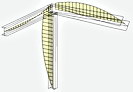
In addition, especially for the formation of wind load on a structure intended to serve the radio-relay networks, finite pseudo element of antenna is entered in the program, whose sole function - generate and transmit wind load on the structure. The program maintains a database of typical antennas, numbering about 2,500 antennas from different manufacturers. If necessary, the user can fill this base oneself.

   Panel High band antennas
   Directional antennas (Yagi, Logo, Helix)
   Omnidirectional antennas
   Panel Low band antennas
   Dipole antennas
   Turnstile antennas
   RRL antennas
   Remote units

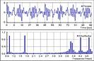
Fluctuating component of the wind action is also formed extremely easy - just specify the number of the static loading which corresponds to the static wind component. The program will automatically convert static component in fluctuating oneself. The results of the analysis are the amplitudes of the nodal displacements, forces and stresses in the elements of the current wind pulsation components. These results correspond to the the level of static load component of the wind loading - normative values of the static component correspond to normative values of the pulsation components, the calculated – to calculated.

( ReadReduce )


Wind resonans

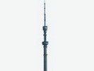
Calculation of the tower structures and chimneys due to the vortex excitation (wind response).

Under certain wind speeds generated vortex shedding from the lateral edges of the structures (towers, chimney), who begin to rock structure in the transverse direction relative to the wind flow. The most dangerous is the condition where the vortex shedding frequency coincides with one of the natural frequencies of the structure.

The regime allows you automatically form a dynamic load acting across the wind flow. In addition, the program automatically generates static and pulsation wind components, corresponding to a given resonance effects.

( ReadReduce )


Seismic

Calculation on seismic action is performed based on the linear-spectral method. The calculation can be made in accordance with the requirements of SNiP II-7-81, DBN B.1.1-12: 2006 and NP-031-01.

In all cases, the inertial load is decomposed according to the mode shape of building. For each mode of vibration the dynamic factor is introduced, calculated on the basis of spectral properties of the seismic action and a number of factors, taking into account the structural features of buildings.

The results of analysis are the amplitudes of the nodal displacements, forces and stresses in structural elements.

( ReadReduce )


Lanes

Construction and rolling-on the lanes. The program allows you to build and produce lanes knurled of displacements, efforts, stresses and support reactions.

To construction the lane it is necessary to build routes of the lanes knurling. The user can specify any number of independent routes simultaneously.

The mobile load is formed as a series of vertical forces. Each force is tied to a particular route and fixes respect to the first force, entered on the route.

( ReadReduce )


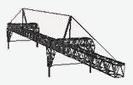
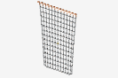
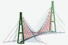
Cable structures calculations

The program performs both static and dynamic analysis of cable and cable-stayed grid nets. The program can solve equally well the problems as with highly stretched strings and with hanging down heavily cables because the exact solution for the rope is laid as a basis of solution. Also another feature of the program is that the rope may be considered as multimass system, which enables to adequately take into account its interaction with the structure under dynamic effects.

In addition to ordinary static and dynamic calculations the program provides a number of specialized calculations for cable structures, making it possible not only to check the bearing capacity of the structure, but also to pick up its options at the best way.

( ReadReduce )


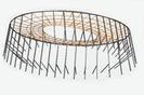
Cable grid net calculation

Under a cable grid net is understood the systems, some nodes of which are formed exclusively by jointed ropes (threads). Masses and dampers may be attached to these nodes, but any other elastic elements can’t be attached to them. It can be various grids attached to an elastic structural elements, dangling threads, dangling grids. If, for example, guy lines of mast subdivided into several sections, that this system has to be regarded as a cable grid net.

Cable grid net – it is significantly more difficult objects in terms of analysis than just a cable system. The program implements an efficient algorithm for analysis of cable grid nets of any complexity. With the same success the program solves both static and dynamic problems. For example, in the accompanying this item demo shows the movement of freely suspended grid after being hit by massive body.

( ReadReduce )


Adjusting the tension of the guys

This mode allows you to build a program of guys tension adjustment (cable-stayed guy), if we know the initial tension of the guys, and the design tension, corresponding to a given load. If the structure contains n controlled cable-stayed elements, the control program permits you to go from initial state to a final in n steps.

To perform the calculations it is necessary to set the initial tension of the guys, the guys design tension, and adjusting order. The result of the calculation is the values of guy’s tension in adjustment process.

( ReadReduce )


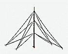
Defining project tension guys for masts

This mode allows you to determine the optimal design guy’s tension for masts. Algorithm of solution constructed in such a way that provides the desired deformation of the mast at the lowest pressing force of structure, which positively affects on the construction buckling.

The program can work in two modes: the selection of cable tension with the given cables’ parameters and selection cables’ tension with parallel selection ropes’ section. The result of this calculation is the design cables tension, optimal cables section and stress state on all construction by all specified static loadings.

( ReadReduce )


Shells generation

The program allows you to create different kinds of shells, covering them with high-quality triangular meshes. 8 different types of generation facilities:

   Generation of spheres
   Generation of surfaces of revolution
   Generation of shallow shells of revolutio
   The generation of planes
   Generation by translationй
   Generation of quadric surfaces
   Generation of surfaces given by algebraic expression
   The generation of surfaces in the assembly

You can use concentrators and introduce fixed nodes into the mesh. The software allows to built shells intersection and cut them by different bodies. Generation of assembly allows you to generate a group of planes, forming a kind of coherent structure (for example, a node structural). The program itself provides the conjugation of planes boundaries. Several independent areas can be generated simultaneously. Relative location of independent regions can be completely arbitrary.

( ReadReduce )


Combinations of loads

Combinations - finding the most unfavorable combination of loads in concordance with various calculation factors. The calculated combination may include simultaneously static, harmonic, pulsation wind, seismic loading, a stationary random process, the dynamic random effects, lanes rolling.

Calculation of the unfavorable combination of loads is performed based on the combination of graphs. The graph is represented by combinations of a set of points that are pairwise connected by segments of curves (arcs). Each arc of the combination graph means a loading, on the action of which had been calculated. The combination of loads is depicted in the graph as a continuous sequence of arcs forming a path from the initial vertex to the destination. The result of calculation for each item are the maximum (minimum) value for each selected calculation factors (force, stress), the corresponding forces and stress and loadings combinations, which ensured the extreme value of the estimated factors.

( ReadReduce )


Construction the diagrams of warping and bimoment on finite element models of rods

The program allows you to build the diagrams of warping and bimoment on finite element models of rods. Each rod is divided onto 20 sections and according to the results of analysis of finite element model the integrals are calculated

where d и В - warping and bimoment in the section, un and sn - normal displacements and normal stresses in the cross section, w - sectorial coordinate of the section point, Jw - sectorial moment of inertia. This feature is useful for the construction units analysis.

( ЧитатьСвернуть )


Vibromonitorig

In engineering practice, there is often appear a problem - to assess the functionality of a structure on which a certain production line is installed, including rotating elements: rotors of motors, shafts, drums, etc. The effect of such elements is the increased vibration of the structure, which in some cases may even lead to its destruction. The cause of the vibration is small eccentricities of rotating elements that cannot be measured "manually". The task is to build an adequate design scheme for the excitation of a structure based on indirect telemetric measurements.

Due to the possibility of setting the dynamic centrifugal inertia forces in the program, and the built-in module of treatment of stationary random processes, the vibration monitoring mode allows you to reconstruct the real scheme of the structure excitation based on the accelerograms. That makes it possible to predict the work of the structure in other heavier modes.

( ЧитатьСвернуть )


Moving dynamic load

To perform calculation on the moving dynamic load it is necessary to build lanes routes. The user can specify any number of independent routes simultaneously, and to put on them independent dynamic forces, synchronize them in time.

Inertia of the moving mass is ignored. However, the values of the driving forces can be added by the component varying sinusoidal. The frequency of the dynamic component can be specified for each individual force. It can be set either a cophasal, or a random-phase mode changed dynamic component of the moving forces.

The results of this analysis are the diagrams changes over time of nodal displacements, forces and stresses in structural elements. The overall picture of deformation can be represented in a multiplicative way.

( ReadReduce )